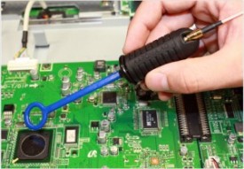
There must be a source, path and receptor for an EMC event to occur. If a radiated or conducted problem is observed during compliance testing, how do we quickly locate the source of undesired RF energy? Many engineers will start to use a near-field probe of some sort and sniff to find where undesired energy appears to be coming from. We sometimes use current clamps to determine if there is a field present on cable assemblies, generally external to the system.
Near-field probes help determine an approximate location of where EMI is present, but not what caused the field to be developed, only the fact it exist. Junior EMC engineers will immediately start replacing discrete components such as decoupling capacitors at random hoping to find a solution without thinking about the problem and why it exist. Rarely do EMC engineers have the schematic of a printed circuit board, or are able to understand logic circuity and perform analysis at the at the component level that includes transmission line routing internal to a PCB. Those working in the field of EMC are not logic designers nor are they experts in material science.
Using only a spectrum analyzer and probes to assess the magnitude of change may provide a false sense of security, since we are investigating near-field emissions which are usually different in the far field; magnetic versus electric with regard to transmission line impedance in free space. When locating the source of RF energy, on a transmission line which many call a trace (in reality all traces are transmission lines), I prefer to use a high bandwidth oscilloscope instead of a spectrum analyzer and work in the time domain instead of frequency domain to locate losses within the transmission line.
The magnitude of a signal integrity problem due to losses in any transmission line is the magnitude of common-mode current developed (per Kirchhoff’s and Ampere’s law). Common-mode current will find a means to propagate in free space or couple to adjacent to transmission lines. A signal integrity problem, especially at high frequencies, is usually the result of poor transmission line implementation and routing within a printed circuit board layout. Therefore, how do we know when a propagating signal within a transmission line, if not analyzed with an oscilloscope, is the cause of an undesired propagating field if we only use a spectrum analyzer in an attempt to fix the problem? Spectrum analyzers only tells us the presence of a field, not what caused to field to be created. Mitigation is difficult for those not knowledgeable in logic design and transmission line routing.
One must be knowledgeable with transmission line theory in the time-domain as well as observing RF in the frequency domain. Remember, in order to solve any transmission line problem, one must be comfortable using different instrumentation and tools. If we are weak within the field of circuit design and analysis or transmission line theory, and most EMC engineers have never done logic design or created a printed circuit board, now is the time for to learn by attending public or private courses, conferences and reading textbooks. A great resource to learn everything about the field of EMC can be discovered in my newest book, EMC Made Simple-Printed Circuit Board and System Design.
Please follow and like us:

Leave a Reply